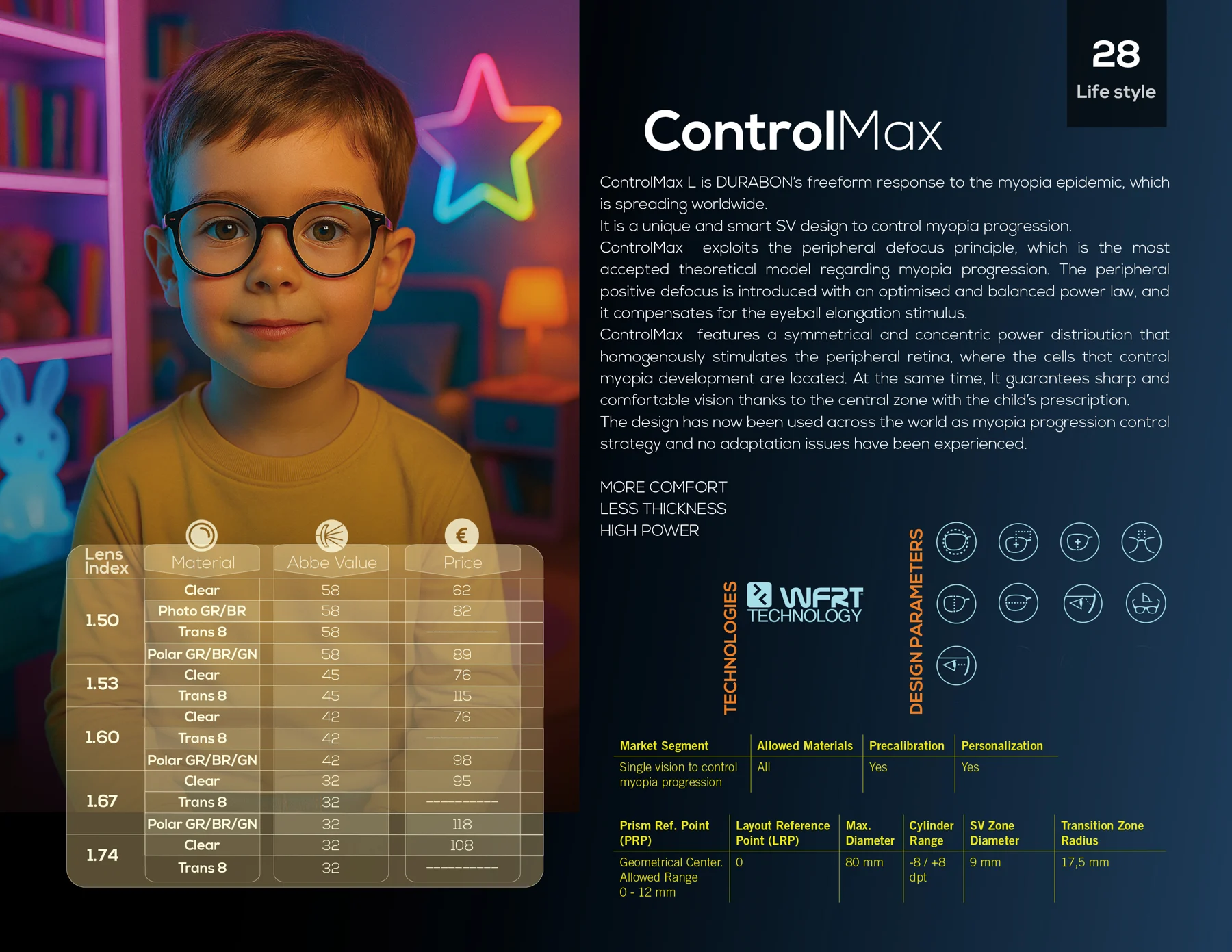
This product is described as a myopia-management design with a central single-vision zone. Selection and follow-up require professional assessment; individual treatment outcomes or arrested progression are not guaranteed.
Application and design rationale
Central zone and peripheral power distribution
The specifications list a 9 mm central single-vision zone and an 80 mm maximum diameter. Selection and outcome assessment form part of professional myopia management.
Design specifications alone do not demonstrate clinical effectiveness for every wearer. Initial assessment and regular follow-up are performed by a practitioner.
| Design identifier | Description |
|---|---|
| Category | Specialist single-vision design for managing myopia progression |
| Design type | Concentric Peripheral Defocus Lens |
Technical specifications
Orderable options depend on prescription, material and current product availability.
| Technical parameter | Value / status |
|---|---|
| Product classMarket Segment | Single vision to control myopia progression |
| Single-vision zone diameterSV Zone Diameter | 9 mm |
| Transition-zone radiusTransition Zone Radius | Confirmation needed; discrepancy 17.0 / 17.5 mm In the text and table |
| Maximum diameterMax. Diameter | 80 mm |
| Cylinder rangeCylinder Range | −8.00 to +8.00 D |
| Available materialsAllowed Materials | All materials |
| Pre-calibrationPrecalibration | Yes |
| PersonalisationPersonalization | Yes (full personalisation) |
| Prism reference pointPrism Ref. Point (PRP) | Geometrical Center |
| Fitting reference pointLayout Reference Point (LRP) | 0 |
| DRP / Inset / Addition | Not stated (single-vision lens) |
| PRP decentration range | 0 to 12 mm |
| Specified indices and options | Refractive indices 1.50, 1.53, 1.60, 1.67 and 1.74; confirm final availability when ordering. |
Design mechanism and features
Central zone and peripheral design
ControlMax is described as single vision with a 9 mm central zone and peripheral-defocus structure, aimed at managing myopia progression. Geometric specifications alone do not establish clinical effect size.
Transition zone
The file gives a 17.5 mm transition-zone radius in the table and 17.0 mm in the reference text. This is not presented as a definitive manufacturing value pending final technical confirmation.
Production and fitting range
The table gives 80 mm maximum diameter, cylinder −8.00 to +8.00 D and active personalisation. This does not establish suitability for every corneal disease. Align the viewing-zone centre with actual PD and height.
Selection and follow-up
Myopia-management prescription and monitoring require professional assessment. This file does not establish guaranteed arrest of axial elongation, guaranteed outcomes or identical clarity for every wearer.
Technologies in this design
- DuraTrace
- Ray-tracing calculations and optical-aberration optimisation in surface design.

Measure before manufacture
Required parameters vary by design and must be recorded by a professional.
- Monocular PD
- Each eye's pupillary distance is recorded separately to align horizontal lens positioning with the visual axis.
- Fitting Height
- Fitting height is recorded on the adjusted frame in the natural position of wear; the required near zone must also fit within the frame.
- BVD
- Distance from the rear lens surface to the corneal apex; relevant to power-compensation calculations in personalised models.
- Pantoscopic Angle
- The frame's vertical tilt in the position of wear must be measured; example values are not substitutes for measurement.
- Wrap Angle
- The horizontal curvature of the frame relative to the face, describing lens positioning.
- Box A
- Horizontal width of the frame opening in the boxing system.
- Box B
- Vertical height of the frame opening in the boxing system.
- DBL
- Distance between the two lens boxes at the frame bridge.
- ED
- Effective diameter: twice the greatest distance from the boxing centre to the lens-shape edge, used for blank selection and edging calculations.
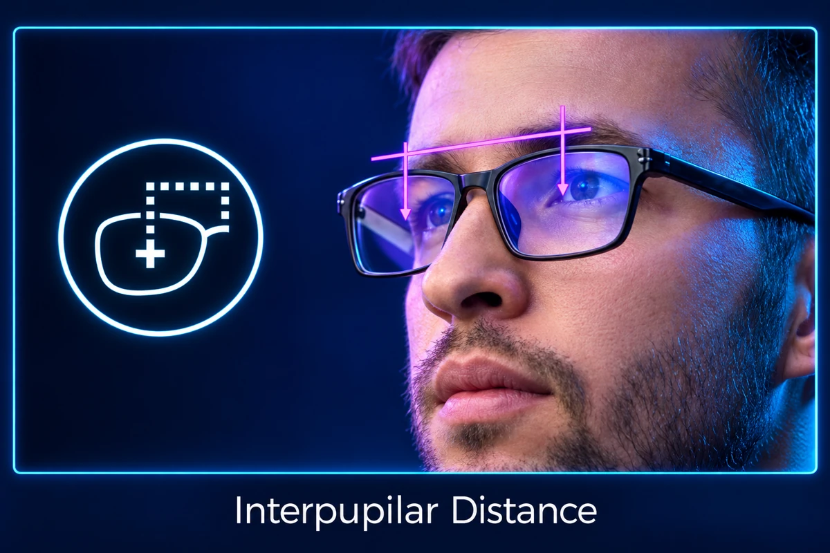
Monocular pupillary distance
For aligning the lens centre with each eye's visual axis.
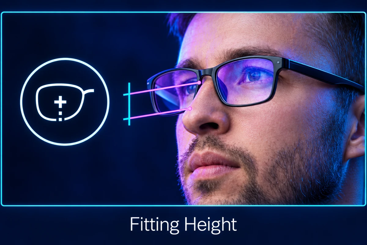
Fitting height
Vertical pupil position relative to the frame in the position of wear.
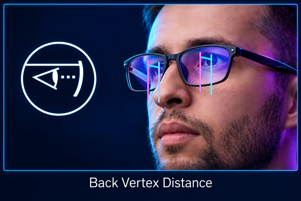
Back vertex distance
One of the inputs describing the actual position of wear.
These are basic fitting parameters; additional inputs and the level of personalisation are specified for each model.
Complete parameter guide ↖View the original catalogue page